![]()
![]()
Assembling a satellite ground station can take many paths, and with the advent of the "Phase 3D era" (P3D), the amateur satellite operator has even more options. The advice common in the last several years may be considerably "dated," as it is most often targeted at Low Earth Orbit (LEO) satellite operation or the venerable AO-10-which often have conflicting requirements. P3D offers the opportunity to do things a little differently. Presented here are a couple of antennae designs ideally suited for the P3D operator on a budget-or perhaps one with an inclination towards home-brewing. These designs are just one combination of suitable solutions and are not intended to describe the optimum system-merely one that will work well for a minimum investment.
Introduction:
One of the most often cited obstacles to entry into the world of amateur satellites is the cost of the large and expensive U/V array typical of an "OSCAR class" station. These large arrays are de-rigour for many serious satellite operators to work AO-10; where 15 to 18 dBi gain is needed to communicate reliably at apogee. But does P3D have these same requirements?
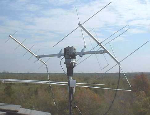
These antennae are elementary and scalable designs. They are practical, easily replicated, and inexpensive to build. Included are a pair of beams for 2 meters and 70 cm and a novel helix design for 13 cm. The builder may choose to employ fixed circular polarity or use switch-able polarity. These antennae are designed with the AMSAT-DL recommendations as a prime guideline and are smaller than the "OSCAR class" described above-much smaller (1). This smaller size leads to less gain. Less gain means wider beamwidth. Wider beamwidth allows less-critical pointing. The inference one may make is automated (and expensive) tracking is not mandatory for P3D. To this end, I offer below designs for 2 meters and 70 cm that will all fit within an imaginary 5' by 5' (1.5 m x 1.5 m) box and can be controlled with TV-type rotors or pointed manually. The final configuration I ended up with is shown above and uses 32" booms for both antennas.
These antennae, while designed with P3D parameters in mind, are suitable for all classes of satellites, from LEO's to P3D to AO-10. They have a little too much gain to work LEO's Without elevation control, but they have no problem working ANY current LEO if pointed at it. They do not have quite enough gain to work AO-10 at perigee, but they easily work it out to 30,000 km.
Modes of Operation:
Mode V/U is the most prevalent combination in use today for LEO's, but not likely to be as popular for P3D. The numerous U/V stations equipped for AO-10 will likely be the initial contingent to populate P3D. Very quickly, though, mode U/S is staged to become the preferred combination (followed by L/S in a few years). The transition to mode U/S will be quite easy for the AO-10-equiped station to simply add a mode-S downconverter using VHF as the IF. Perhaps the idle AO-13 stations will dust off the gear and become active again. For the new P3D station builder, a 2 meter antenna may even be superfluous!
With the preceding in mind, I will describe three antennas designed and built as prototypes in January 2000. The antennas were tested for only a short period, as the author had to leave for an extended stay in Russia. The results for the beam antennae were exactly as expected; the author worked stations on RS-13, AO-27, SO-35, AO-10, FO-20, and FO-29 over a three week period and confirmed the modeled performance for gain and F/B ratio.
UHF / VHF Beam Design Considerations:
The effort began as a design exercise. The original design criteria for the 70 cm and 2 meter antennas were (in order of importance): 1) circular polarity, 2) gain of at least 10 dBi (per AMSAT-DL), and 3) F/B ratio of at least 20 dB. I started with the intent of using 3 x 3 elements on 2 meters and 4 x 4 on 70 cm. Modeling, however, quickly showed me that I needed 4 elements to reach the 10 dBi goal and still have a dimensionally-tolerant design with acceptable bandwidth. Once committed to a 4 x 4 design on 2 meters, I opted to increase the 70 cm design to 6 x 6 elements since I had the physical space now defined by the 2 meter antenna's boom. Both antennas were systematically developed using K4VX's YagiMax 3.46, verified for behavior in NEC4Win95, and empirically tested using available analog satellites.
The antennas are designed as linear Yagi-Uda beams, but employing a folded dipole driven element and a phasing line for circular polarity. The physical construction of the folded dipole driven element provides a 4:1 transformation of the nominal dipole feedpoint impedance (2). Thus, the antennae are designed with a 25 Ohm dipole feedpoint, but constructed with a folded dipole element, resulting in a 100 Ohm feedpoint impedance. Then, two of these linear beam antennas are coupled together in parallel fashion via a 93 Ohm (RG-62) coaxial cable, producing a summed feedpoint impedance of (approximately) 50 Ohms. Circular polarity is effected through a 90 degree phase shift inherent in a � wavelength section of coaxial cable. This simple, effective scheme is shown in Figure 1 below and described in detail in The Radio Amateur's Satellite Handbook (3). A builder can choose to avoid the complexity of the relay and simply employ the circular polairty phasing method shown for both the Eggbeater II and the Texas Potato Masher II antennas. The 70 cm antenna produces approximately 12 dBi of gain with a 24 dB F/B ratio and the 2 meter antenna produces a very respectable 10.6 dBi gain with a 23 dB F/B ratio.

UHF Beam Construction-6 x 6 Elements:
The prototype antenna is constructed using 3/4" (19 mm) PVC piping and # 10 AWG insulated
copper wire (0.1" (2.5 mm) diameter of conductor). The driven element is 10-5/8" x 1-1/8" in size. The dimensions are given below in Table 1.
| Element: | Length (in. / cm) | Distance (in. / cm) |
| Reflector | 13.375 / 34.0 | 0.00 / 0.0 |
| Driven Elem. | 12.450 / 31.6 (x 2) | 5.75 / 14.6 |
| Director 1 | 11.935 / 30.3 | 11.00 / 27.9 |
| Director 2 | 11.875 / 30.2 | 16.00 / 40.6 |
| Director 3 | 11.815 / 30.0 | 23.50 / 59.7 |
| Director 4 | 11.685 / 29.7 | 32.00 / 81.3 |


Figure 3: The UHF/VHF Beams During "Field Trials"

Figure 4: 70 cm beam feedpoint arrangement inside a PVC coupling.
As is visible in Figure 3 above, I did not have elevation control available for testing the antenna, but I did manage to work quite a few low-elevation passes of various LEO's with moderate success (with the antenna set at about 15 degrees elevation). I made it into SO-35's very(!) competitive transponder at the northern LOS with this antenna, whereas I could never accomplish that feat with my "everyday" TPM II (4). I was also able to work AO-10 with ease out to 30,000 km using 100 Watts: working both New Zealand and Europe from Texas with 55+ signals on SSB (between the fades, of course).
VHF Beam Construction-4 x 4 Elements:
This antenna was also constructed using 3/4" (19 mm) PVC piping, but the author recommends
using 1" (25 mm) material as the boom sag on the prototype was noticeable. The elements are
fabricated from 1/4" (6.35 mm) copper tubing; the kind used for refrigerator water hookup. This material is very soft and easy to work with, but would not be suitable for areas where snow is a frequent visitor. Aluminum tubing or 3/16" (5 mm) rod are commonly available and would make better candidates for a long-term-use antenna. The driven element is formed using #10 AWG insulated wire. The nominal dimensions are given below in Table 2. If 3/16" rod is used, follow the dimensions give in Table 3.
| Element: | Length (in. / cm) | Distance (in. / cm) |
| Reflector | 39.375 / 100.0 | 0.0 / 0.0 |
| Driven Elem. | 38.400 / 97.5 (x 2) | 17.0 / 43.2 |
| Director 1 | 36.500 / 92.7 | 36.0 / 91.5 |
| Director 2 | 36.250 / 92.1 | 56.0 / 142.2 |
| Element: | Length (in. / cm) | Distance (in. / cm) |
| Reflector | 39.463 / 100.2 | 0.0 / 0.0 |
| Driven Elem. | 38.168 / 96.9 (x 2) | 17.0 / 43.2 |
| Director 1 | 36.774 / 93.4 | 36.0 / 91.5 |
| Director 2 | 36.539 / 92.8 | 56.0 / 142.2 |

AO-10 performance, the real test for a 2 meter satellite antenna, was outstanding, as the ability to switch circular polarity made this the better performer when directly compared to my 7-element horizontally-polarized antenna (5). On uplink, I could reach beacon strength on CW into RS-13 with 5 Watts. I really hated to take this antenna down.
VHF Beam Construction-3 x 3 Elements:
This antenna is the one I ultimately constructed for use on P3D using 3/4" (19 mm) PVC piping and elements fabricated from 1/4" (6.35 mm) aluminum tubing. This antenna models at a gain of 8.5 dBi and a F/B ratio of 17 dB--not nearly as good as the 4 element version, but the boomlength is only 32" (81 cm), the same as the 6x6 UHF beam. This combination provided me with a very low profile system--necessary in my deed-restricted neighborhood . See the picture at the top of the page for the installed antennae. The driven element is, again, formed using #10 AWG insulated wire and is 34-1/4" x 4" in size. The nominal dimensions are given below in Table 4.
| Element: | Length (in. / cm) | Distance (in. / cm) |
| Reflector | 39.500 / 100.3 | 0.0 / 0.0 |
| Driven Elem. | 39.000 / 99.0 (x 2) | 17.0 / 43.2 |
| Director 1 | 36.250 / 92.1 | 32.0 / 81.3 |

References:
1. Frank Sperber, AMSAT-DL Journal; see: http://www.qsl.net/dl6dbn/amsat/adlj-bod.htm
2. The ARRL Antenna Book, 16th Ed., ARRL, 1992, pp. 2-32, 4-8.
3. Davidoff, Martin, The Radio Amateur's Satellite Handbook, ARRL, 1998, pp. 9-4 - 9-6.
4. Brown, Gerald R., "The Texas Potato Masher II Antenna," Oscar Satellite Report # 413, September 1, 1999; or see: http://members.aol.com/k5oe/tpm2.htm.
5. Brown, Gerald R., A Modest AO-10 Antenna, The AMSAT Journal, Jan. 1999; or see: http://members.aol.com/k5oe/ao-10.htm
(C) 2000, Gerald R. Brown, K5OE