Patented Oct. 18, 1949
UNITED STATES PATENT OFFICE
2,485,457
ANTENNA SYSTEM .
Ralph K. Potter, Morristown, N. J., assignor to Bell Telephone laboratories, incorporated, New York, N. Y., a corporation of New York
Application October 30,1944, Serial No. 559,559
4 Claims. (CI. 250—33)
Данный патент зарегистрированный в 1949 году описывает конструкцию антенной системы, которая может заинтересовать радиолюбитей. Конструкция достаточно простая, компактная, имеет одну точку подвеса. К сожалению статья на английском языке, но можно воспользоваться переводчиком из Google.
This invention relates to antenna systems and particularly to flexible transmitting dipole antenna systems.
As is known, half-wave dipoles termed herein "conventional dipoles" and comprising two go-linear wires, and rugged vertical half-wave "coaxial dipoles" of the type disclosed in Patent 2Д84,729 to A, B. Bailey, are employed in the high frequency and very high frequency fields for transmitting a large amount of power. In general, these relatively heavy transmitting half-wave dipoles and associated transmission lines require rigid supporting structure and are usually attached, at the dipole mid-point, to the supporting structure. Ordinarily, the band widths of these prior art rigid transmitting dipoles are relatively narrow and therefore not entirely satisfactory. Accordingly, it now appears desirable and advantageous to obtain a flexible high power transmitting dipole having a relatively wide baud width characteristic.

It is one object of this invention to obtain a flexible transmitting dipole antenna having a broad band width.
It is another object of this invention to secure a portable, easily supported or suspended, iiigh power dipole of simple construction.
It is still another object of this invention to secure a high power transmitting dipole antenna whiGh does not require support at its mid-point.
In accordance with one embodiment of the invention a high power transmitting dipole comprises a vertical coaxial line having an inner conductor extending above and beyond the outer conductor a distance of approximately a quarter wavelength. At a point about a quarter wavelength from the end of the outer conductor the line is coiled to form an impedance. The coil functions to resonate the half-wave coaxial line section above the coil, that is, to secure dipole action, and to prevent the flow of spurious currents on the outer surface of the remaining outer conductor portion below the coil. The uppermost extremity of the inner conductor is attached through an insulator to a support. While the dipole antenna is especially suitable for transmitting radio waves it may, of course, be used for radio reception.
The invention will be more fully understood | from a perusal of the following specification taken in conjunction with the drawing on which like reference characters denote similar elements and on which:
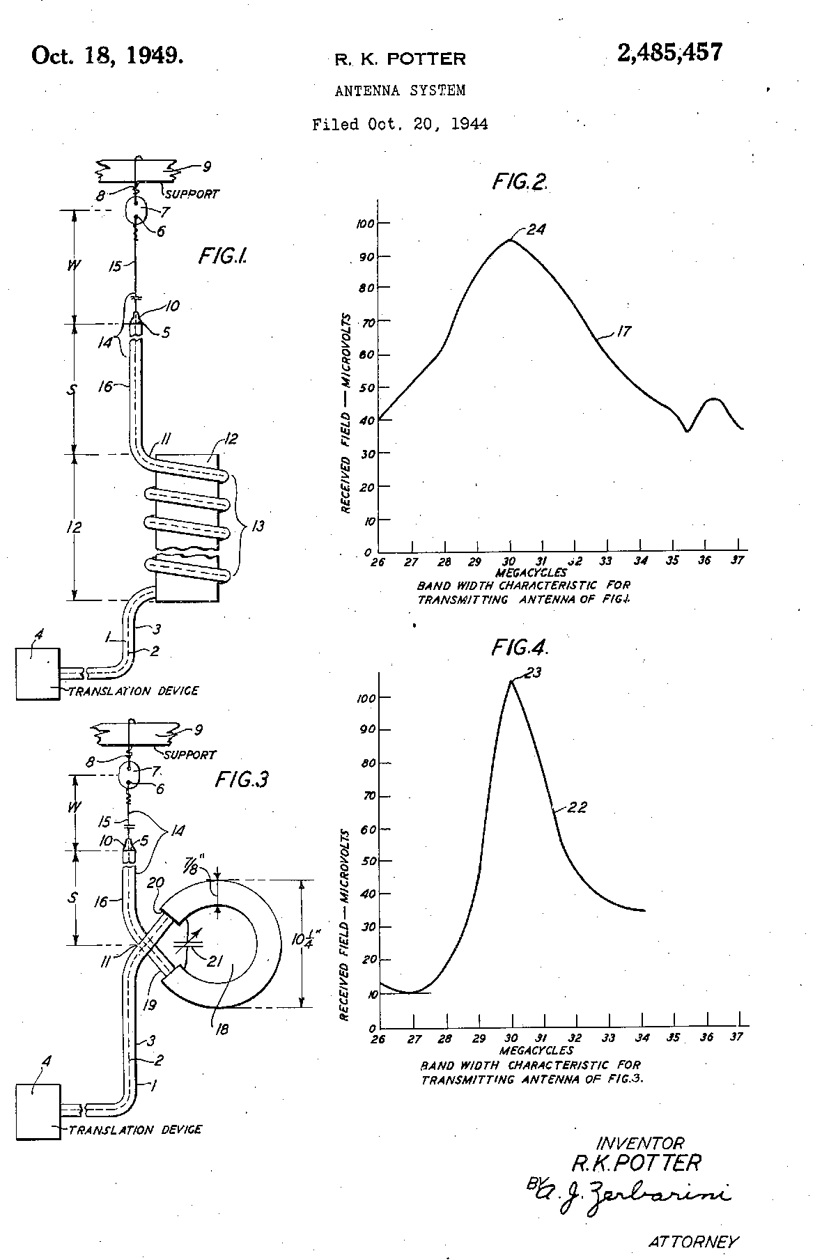
Fig. 1 is an elevational view of one embodiment of the invention, and Fig. 2 illustrates the band width characteristic for the embodiment of Fig. 1;Fig. 3 is an elevational view of a different embodiment of the invention, and Fig. 4 illustrates 5 the band width characteristic for the embodiment of Fig. 3.
Referring to Fig. 1, reference numeral I denotes a coaxial line comprising an inner conductor 2 and an outer conductor 3. The line 1 is connected at its near end to a translation device 4, such as a very high frequency transmitter; and the portion of the line adjacent the remote end is vertically positioned. The inner conductor 2 extends above and beyond the extremity 5 of the outer conductor 3 a distance W approximately equal to a quarter wavelength at the means or design operating frequency. The extremity 6 of the inner conductor 2 is secured through insulator 7 and guy wire 8 to the supporting member 3; and the outer conductor 3 is supported at its extremity 5 by insulator 10 and the inner conductor 2. At a point 11, located at a distance S approximately a quarter wavelength below the extremity 5, the line i is bent or coiled about the tubular insulator 12 so as to form a multiple turn impedance coil <3. As explained below, the section 14 of line I extending above point JI and comprising the exposed inner conductor section or "whip" (o and the outer conductor section or "skirt" 16 functions as a dipole antenna over a broad frequency range.
In operation, waves of a given frequency are supplied by the high power transmitter 4 over the lower portion of line I and coil 13 to the upper line portion 14 and thence radiated. The coil i 3 causes the upper line portion to resonate at the operating frequency and therefore to function as a dipole. As is the case of an ordinary vertical dipole, the directive pattern is substantially non-directional in the horizontal plane and somewhat directional in the vertical plane, the direction of maximum action in the vertical plane being horizontal.. The coil 43, or more accurately, the coiled portion of the outer conductor 3, functions as a high impedance whereby the flow of spurious currents along the outer surface of the center conductor 3 is prevented.
In a system actually constructed in accordance with Fig. 1, the lengths W and S of the whip and skirt elements 15 and 16 were 90.5 and 82.5 inches, respectively. A tubular insulator 12 having a diameter of 5 inches and a length of 12 inches was utilized; and a coil 13 having twelve turns was employed. In a frequency test of the system, the frequency of the transmitter 4 was varied over the 26-37 megacycle range and the transmitted waves were received at a point spaced approximately 700 feet from the transmitting antenna 14. As shown by the curve 17, Pig. 2, which illustrates the measured band width characteristic of the system, maximum energy was received when the frequency was approximately 30 megacycles. For all frequencies in the band, the received energy was at least 40 microvolts. The curve 17 is fairly flat, relatively considered, so that the dipole has a fairly broad band width characteristic.
The embodiment illustrated by Pig. 3 differs from the system of Fig. 1 in that a single turn tuned coil 18 is employed at point 11 of line I in place of the multiple turn coil 13. The coil 18 comprises a single turn 19 of line 2, a tubular member coaxially enclosing the coil 19 and an adjustable condenser 2 i connected in shunt with the tubular member 20. As in the system of Fig.1 waves are supplied by the transmitter over line 2 and coil 18 to the dipole 14 and thence radiated. The band width of the antenna of Pig. 3, while relatively broad, is somewhat more narrow than that of the system of Fig. 1 inasmuch as the single turn coil 18 and shunt condenser 21 function to produce sharper resonance.

In a system constructed in accordance with Fig. 3, the lengths W and S of the whip 15 and skirt 16 were respectively 93.5 and 92 inches. The outside diameter of the tubular member 20 was 7/8 of an inch and the outside diameter of coil 18 was 10.25 inches. As shown by the band width curve 22, Fig. 4, the coil 18 produces maximum resonance at 30 megacycles. While the energies received at the frequencies in the central portion (29-32.5 megacycles) of the band were greater than 40 microvolts, the energies received at frequencies included in the two end portions of the band, 27-29 and 32.34 megacycles, were of small intensity, so that the system of Fig. 3 has, as compared to the system of Fig. 1, a narrow band width characteristic. At the mid-point of the band, however, the power transmitted by the dipole of Fig. 3 is greater than that transmitted by the dipole of Fig. 1, as shown by the fact that the peak or nose 23 of curve 22, Fig. 4, is above 100 microvolts and higher than the peak 24 of curve 17, Fig. 2, which is below 100 microvolts.
Although the invention has been explained in connection with certain embodiments, it is to be understood that it is not limited to the embodiments described inasmuch as other apparatus may be employed in successfully practicing the invention.
What is claimed is:
1. A transmitting dipole antenna comprising a coaxial line having an inner conductor and an outer conductor, said inner conductor being longer than said outer conductor, means for resonating said dipole comprising an inductive coil including in said line at a point substantially a quarter wavelength from the extremity of the outer conductor and having approximately twelve turns.
2. In an antenna system, a transmitting dipole antenna comprising a coaxial line having an inner conductor and. an outer conductor, said inner conductor being substantially a quarter wavelength longer than the outer condcutor, said line being coiled at a point substantially a half wavelength from the extremity of the inner conductor, the coiled portion of said coaxial line forming an inductive coil having only a single turn, a tubular shield coaxially enclosing said coil and an' adjustable condenser connected in shunt with said shield.
3. In an antenna system, a coaxial line having an inner and an outer conductor, said inner conductor extending a given distance beyond the extremity of the outer conductor, said inner conductor being coiled at a point spaced from said extremity a distance substantially equal to said first-mentioned distance, the line section included between said point and the extremity of the inner conductor constituting a dipole having an effective electrical length one half of a given wavelength, the dipole and the coiled portion of said inner conductor being highly resonant over a broad band of wavelengths including said given wavelength.
4. In an antenna system, a vertical coaxial line having an inner conductor and an outer conductor, said inner conductor extending above the extremity of the outer conductor substantially a quarter wavelength as measured at a frequency included in a given band, means for substantially resonating over said band the exposed quarter wave portion of said inner conductor and the upper quarter wave end portion of said outer conductor comprising a coiled portion of the inner conductor located on said line substantially a quarter wavelength below said extremity, means for preventing the flow of undesired currents on the outer surface of the outer conductor portion comprising a coiled portion of the outer conductor coaxially enclosing said first mentioned coiled portion.


The following references are of record in the
file of this patent:
UNITED STATES PATENTS
Number Name Date
2,036,456 Buschbeck__________Apr. 7, 1936
2,094,168 Forbes____________Sept. 28, 1937
2,097,491 Lair________________Nov. 2, 1937
2,102,410 Fyler______________Dec. 14, 1937
2,158,875 Leeds______________May 16, 1939
2,184,729 Bailey______________Dec. 26, 1939
2,207,263 Nass________________July 9, 1940
2,208,413 Erben______________July 16, 1940
2,274,389 Von Baeyer et al_____Feb. 24,1942
2,297,513 Von Baeyer________Sept. 29, 1942
FOREIGN PATENTS
Number Country Date 65 857,245 France_____________Apr. 15, 1940
