How to control a HD44780-based Character-LCD
(Industry-Standard-Character-LCD)
Miscellaneous examples
Visitor # counter

line
© 1995-2000 Peter Ouwehand.
Last updated on 2000-12-23
If these pages are stuck in someone elses frame,
click here to open them in a new browser window
Best viewed using 1024x768x256 display mode.
line
line

5. Miscellaneous examples


TOC
line

5.1. PIC16C54 using only 3 lines

This example is donated by Marc Simons. If you have any questions/comments please send E-Mail to msimons@IAEhv.nl.

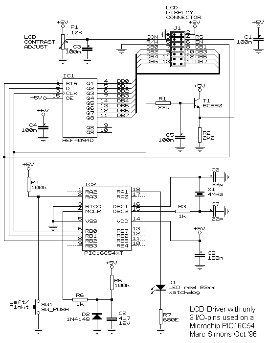
schematic
Shift-Click to download gif.

Brief description:

Pins RB0, RB1 and RB2 are used for controlling AND driving text to the LCD display. Most of the time the PIC's are sufficient enough for most applications, except when it comes to more I/O. This simply cannot be expanded, except when you go to the BIG GUYS like the PIC16C74 etc. where I have done some applications with too. Observe the schematics: An PIC16C54 is the heart of the whole thing. It drives the HEF4094 CMOS serial2parallel converter. This gives us the databus towards the LCD display. Since the HEF4094 strobe is activated at the rising edge, and the LCD display on the falling edge, these can be shared. So, on the rising edge the 4094 spits out it's new byte, and on the falling edge the LCD reads it in. By the way, this concept cannot read out info from the LCD display. (Personal opinion: It is useless anyway!) Now the hard part comes: How to derive 'text' from 'commands'?? The LCD has a pin for it: The RS-pin. When it is clear, commands are accepted. when set, text is accepted. How is it solved?

Before I spit out a character to the HEF4094, I set the clock for 500uSec. Resistor R1 will load capacitor C5. Then, I spit the text character towards the 4094 as soon as possible. Therefore the capacitor simply does not have the time to discharge: The LCD will accept it as text. For commands it is the same, however, of course the other way around: The capacitor must be discharged. T1 forms an emitter follower to buffer the R/C network. The reason for this is that the LCD RS input is an TTL input, so without proper buffering it will not work.

The code contains a few basic routines to handle the LCD display. The switch that I added is purely for fun: To be able to toggle rotation of the text. I used an 16 characters / 2 lines LCD display from an old security keypad. (Go to a surplus electronics store, they always have some!)

P.S. Any suggestions for good code from YOUR side are always welcome! Best Regards from msimons@IAEhv.nl, your PIC Scueezer Weezel!

MSIMONS.ZIP includes the schematics, source code and include file needed for this example.

TOC
line

5.2. .....


TOC

line